Cyber-physical systems as a pillar of Industry 4.0

What is that?

A cyber-physical system (CPS) is used to control a physical-technical process and, for this purpose, combines electronics, complex software and network communication, e.g. via the Internet. One characteristic feature is that all elements make an inseparable contribution to the functioning of the system. For this reason, it would be wrong to consider any device with some software and a network connection to be a CPS.

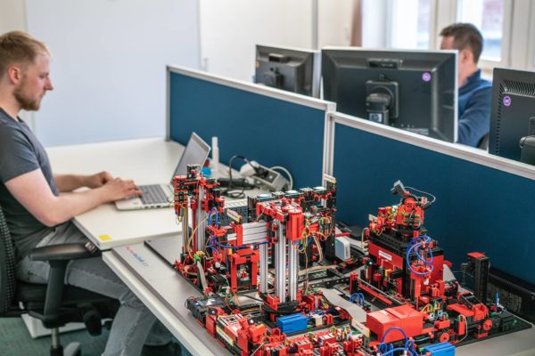
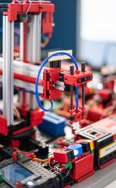
Especially in manufacturing, CPS’ are often mechatronic systems, e.g. interconnected robots. Embedded systems form the core of these systems, are interconnected by networks and supplemented by central software systems, e.g. in the cloud.

Due to their interconnection, cyber-physical systems can also be used to automatically control infrastructures that are located far away from each other or a large number of locations. These could only be automated to a limited extent – until now. Some examples of this are decentrally controlled power grids, logistics processes and distributed production processes.

Thanks to their automation, digitalization and interconnection, CPS provide a high degree of flexibility and autonomy in manufacturing. This enables matrix production systems, which support a wide range of variants at large and small quantities [1].

So far, no standardized definition has been established, as the term is used broadly and non-specifically and is sometimes used to market utopian-futuristic concepts [2].

Where did this term originate?

In recent years, innovations in the fields of IT, network technology, electronics, etc. have made complex, automated and interconnected control systems possible. Academic disciplines such as control engineering and information technology offered no suitable concept for the new mix of technical processes, complex data and software. As a result, a new concept with a suitable name was needed.

The term is closely related to the Internet of Things (IoT). Moreover, cyber-physical systems make up the technical core of many innovations that bear the label “smart” in their name: Smart Home, Smart City, Smart Grid etc.

Features of CPS

As mentioned above, there is no generally recognized definition. But the following characteristics can be destilled from the multitude of definitions:

  • At its core there is a physical or technical process.
  • There are sensors and models to digitally record the status of the process.
  • There is complex software to allow for a (partially) automatic decision to be made based on the status. While human intervention is possible, it is not absolutely required.
  • There are technical means for implementing the selected decision.
  • All elements of the system are interconnected in order to exchange information.

One CPS design model is the layer model according to [2]

Figure 1: Layer model for the internal structure of cyber-physical systems

Examples of cyber-physical systems

  • Self-controlled manufacturing machines and processes (Smart Factory)
  • Decentralized control of power generation and consumption (Smart Grids)
  • Household automation (Smart Home)
  • Traffic control in real time, via central or decentral control with traffic management systems or apps (element of the Smart City)

Example of an industrial cyber-physical system

This example shows a manufacturing machine that can operate largely autonomously thanks to software and interconnection, thereby minimizing idle times, downtimes and maintenance times. Let us assume that we are dealing with a machine tool for cutting as example.

Interconnected elements of the system:

  • Machine tool with
    • QR code camera for workpiece identification
    • RFID reader for tool identification
    • Automatic inventory monitoring
    • Wear detection and maintenance prediction
  • Central IT system for design data and tool parameters (CAM)
  • MES/ERP system

The manufacturing machine of our example is capable of identifying the workpiece and the tool. The common technologies RFID or QR code can be used for this purpose. A central IT system manages design and specification data, e.g. a computer-aided manufacturing system (CAM) for CNC machines. The manufacturing machine retrieves all the data required for processing from the central system using the ID of workpiece and tool. As a result, there is no need to enter parameters manually as the data is processed digitally throughout. The identification allows the physical layer and data layer of a cyber-physical system to be linked.

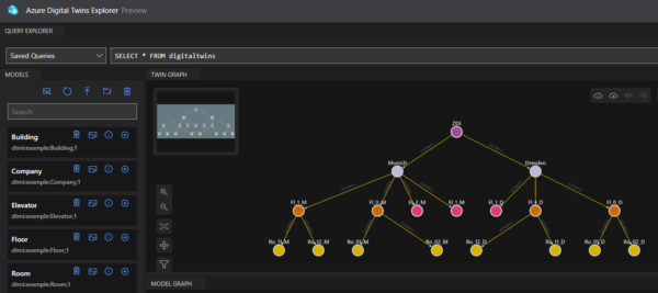
The digitized data for workpieces, machines and other manufacturing elements can be grouped under the term digital twin, which was presented in the blog article “Digital twins: a central pillar of Industry 4.0” by Marco Grafe.

The set-up tools and the material and resource inventories available in the machine are checked on the basis of the design and specification data. The machine notifies personnel if necessary. By performing this validation before processing begins, rejects can be avoided and utilization increased.

The machine monitors its status (in operation, idle, failure) and reports the status digitally to a central system that records utilization and other operating indicators. These types of status monitoring functions are typically integrated into a Manufacturing Execution System (MES) and are now in widespread use. In our example, the machine is also able to measure its own wear and tear in order to predict and report maintenance requirements, thereby increasing its autonomy. These functions are known as predictive maintenance. All these measures improve machine availability and make maintenance and work planning easier.

Through the use of electronics and software, our fictitious manufacturing machine is capable of working largely autonomously. The role of humans is reduced to feeding, set-up, troubleshooting and maintenance; humans only support the machine in the manufacturing process.

References

[1] Forschungsbeirat Industrie 4.0, „Expertise: Umsetzung von cyber-physischen Matrixproduktionssystemen,“ acatech – Deutsche Akademie der Technikwissenschaften, München, 2022.

[2] P. H. J. Nardelli, Cyber-physical systems: theory, methodology, and applications, Hoboken, New Jersey: Wiley, 2022.

[3] P. V. Krishna, V. Saritha und H. P. Sultana, Challenges, Opportunities, and Dimensions of Cyber-Physical Systems, Hershey, Pennsylvania: IGI Global, 2015.

[4] P. Marwedel, Eingebettete Systeme: Grundlagen Eingebetteter Systeme in Cyber-Physikalischen Systemen, Wiesbaden: Springer Vieweg, 2021.

Smart Manufacturing at the office desk

factory out of lego bricks on a desk in an office
Figure 1: Overview of the learning factory in Görlitz

While more and more start-ups, mid-sized companies and large corporations are using digitalisation and networking to expand their business, and are developing entirely new business models, the global demand for standardisation and implementation expertise is growing. For example, real-life technologies have long been evolving from phrases that previously didn’t hold a lot of meaning, like “Big Data”, “Internet of Things (IoT)” and “Industry 4.0”; such technologies are driving digital transformation while helping companies to increase their productivity, optimise their supply chains and, ultimately, increase their gross profit margins. They primarily benefit from reusable services from hyperscalers such as Amazon, Microsoft, Google or IBM, but are themselves often unable to implement tailor-made solutions using their own staff. ZEISS Digital Innovation (ZDI) assists and supports its customers in their digital transformation as both a partner and development service provider.

Cloud solutions have long been clunky – especially in the industrial environment. This was due to widespread scepticism regarding data, IT and system security, as well as development and operating costs. In addition, connecting and upgrading a large number of heterogeneous existing systems required a great deal of imagination. For the most part, these basic questions have now been resolved and cloud providers are using specific IoT services to recruit new customers from the manufacturing industry.

In order to illustrate the typical opportunities and challenges borne by IoT environments in the most realistic way possible, an interdisciplinary ZDI team – consisting of competent experts from the areas of business analysis, software architecture, front-end and back-end development, DevOps engineering, test management and test automation – will use a proven agile process to develop a demonstrator that can be used at a later date to check the feasibility of customer-specific requirements.

A networked production environment is simulated in the demonstrator using a fischertechnik Learning Factory and is controlled using a cloud application developed by us. With its various sensors, kinematics, extraction technology and, in particular, a Siemens S7 control unit, the learning factory contains many of the typical elements that are also used in real industrial systems. Established standards such as OPC UA and MQTT are used to link the devices to an integrated IoT gateway, which in turn supplies the collected data via a standard interface to the cloud services that have been optimised for this purpose. Conversely, the gateway also allows controlled access to the production facilities from outside of the factory infrastructure while taking the strict IT and system security requirements into account.

part of the learning factory
Figure 2: Gripping arm with blue NFC workpiece

Establishing and securing connectivity for employees across all ZDI locations after commissioning has occurred is on one hand an organisational requirement, and on the other, already a core requirement for any practical IoT solution with profound effects for the overall architecture. In terms of technology, the team will initially focus on cloud services offered by Microsoft (Azure) and Amazon (AWS), contributing extensive experiences from challenging customer projects in the IoT environment. Furthermore, the focus remains on architecture and technology reviews as well as the implementation of the initial monitoring use cases. Using this as a foundation, more complex use cases for cycle time optimisation, machine efficiency, quality assurance or tracing (track and trace) are in the planning phase.

ZDI is also especially well positioned in the testing services field. Unlike in extremely software-heavy industries such as logistics or the financial sector, however, test managers for numerous production-related use cases were repeatedly confronted with the question of how hardware, software and, in particular, their interaction at the control level can be tested in full and automatically, without requiring valuable machine and system time. In hyper-complex production environments, such as those that ZEISS has come across in the semiconductor and automotive industries, digital twins, which are widely used otherwise, only provide a limited degree of mitigation as relationships are difficult to model and, occasionally, fully unknown influencing factors are involved. This makes it all the more important to design a suitable testing environment that can be used to narrow down errors, reproduce them and eliminate them in the most minimally invasive way possible.

We will use this blog to regularly report on the project’s progress and share our experiences.


IoT (and more) with Azure Digital Twins

As the Industry 4.0 concepts mature, we will look at the Azure edition of Digital Twins. The definition of Digital Twins assumes the digital representation of real-world things’ (or people’s) properties, either in real time (for control and predictive maintenance) or in simulations to acquire and test behaviors before actual deployment. As such, Azure Digital Twins are closely related to Azure IoT services; however, they could do a bit more, as we will see below.

Symbolical image of a male and a female engineer in a modern manufactory while he uses a tablet to control a machine in the production line

How are models created and deployed?

Azure Digital Twins relies on Digital Twins Definition Language (DTDL), which follows JavaScript Object Notation for Linked Data (JSON-LD), making it language-agnostic and connected to certain ontology standards. Root structure is declared as interface, which can contain properties, relationships, and components. Properties can contain telemetries (event-based, like temperature readings) or values (e.g., name or aggregate consumption), relationships describe connection between Twins (for example, floor contains room), and finally, components are also models referenced in interface per id (e.g., phone has camera component).

Models support inheritance, thus one can already think of these models as serverless (POCOs) classes. Indeed, from these models, instances are created which live in Azure Digital Twins. The logical question arises, if these are somehow classes, what about methods? This is where serverless Azure Functions find its use very well, as all events from Digital Twins can be captured and processed with Azure Functions. Hence, Azure Digital Twins, paired with Azure Functions, create powerful serverless infrastructure which can implement very complex event-driven scenarios by utilizing provided REST API for model and data manipulation. The price for this flexibility is a rather steep learning curve, and one must write functions for data input and output from scratch.

Json models can be created by hand, or even easier, Microsoft provides sample ontologies (prefabricated domain models) available in Excel that can be extended or adapted. Using Digital Twins Explorer (currently on preview in Azure Portal), these models can be uploaded in Azure with already prescribed instance and relationship creation automatization. Underneath Azure Digital Twins Explorer is REST API, so one can also programmatically do this as well.

In our sample smart building implementation (depicted in Image 1) we created and uploaded models (shown on the left) and instances with relations (shown on the graph on the right). There is a company model instance for ZEISS Digital Innovation (ZDI), which has two buildings Dresden and Munich each containing floors, rooms, and elevators.

Screenshot from a programme for modeling Azure Digital Twins
Figure 1: Modeling

How data come into the system?

In our smart building implementation (depicted in Image 2) we utilize IoT Hub to collect sensor data from rooms (temperature, energy consumption, number of people in the rooms, etc.), as well as OPC UA converted data from elevators.

Schematic representation of the architecture of a smart building implementation
Figure 2: Architecture

Normally, IoT Hub easily integrates with Insight Time Series with a couple of clicks out of the box, but some functions are necessary to intercept this data with Digital Twins. The first function reacts to IoT Hub Event Grid changes and propagates updates to Digital Twins, which can then trigger other functions, for example calculating and updating the aggregate energy consumption in the room and propagating this to all parents. All these changes in Digital Twins are streamed to the Event Hub in an update patch format that is not readable by Insight Time Series. Here comes another function which converts these patch changes and streams them to another Event Hub to which Insight Time Series can subscribe and save the data. Sounds over-engineered? It is! As mentioned, there is a lot of heavy lifting that needs to be done from scratch, but once familiar with the concepts, the prize is flexibility in implementing almost any scenario. From vertical hierarchies with data propagations (such as heat consumption aggregations) to horizontal interactions between twins based on relationships (as in when one elevator talks and influences the other elevators’ performance in the same building based on an AI model) can be implemented.

Another powerful feature is that we can stream and mix data from virtually any source in Digital Twins to extend their use for business intelligence. From ERP and accounting systems, to sensors and OPC UA Servers, data can be fed and cross-referenced in real time to create useful information streams – from tea bags that will run out in the kitchen on a snowy winter day to whether the monetary costs for elevator maintenance are proportional to the number of trips in year.

How are the data analyzed and reported?

In many industrial systems, and thanks to increasing cheap storage, all telemetry data usually land in a time series for analytics and archiving.

However, data alarms, averages, and aggregations can be a real asset in reporting in real time. Digital Twins offer full REST API where twins can be queried based on relations, hierarchies, or values. These APIs can be also composed and exposed to third parties in API Management Services for real-time calls.

Another way is to utilize Time Series Insights for a comprehensive analysis on complete data sets or using time series dumps to create interactive reports using Power BI.

Both real-time and historical reporting has its place and optimal usage determination should be based on concrete scenarios.

Summary

Azure Digital Twins offer language-agnostic modeling that can accept a myriad of data types and support various ontologies. In conjunction with serverless functions, very complex and powerful interactive solutions can be produced. However, this flexibility comes with high costs for manual implementation in data flow using events and functions. For this reason, it is reasonable to expect that Microsoft (or an open source) will provide middleware with generic functions and libraries for standard data flows in the future.