Automatic control of complex physical systems is an ever-growing theoretical and technical challenge for scientists and engineers. To begin with, it is irrelevant whether these systems are biological or chemical reactors, wind turbines, power grids, aircraft or even manufacturing systems. In all of these use cases, similar theoretical and practical issues come to the fore. We will look at some of the key ones in more detail in this article. Before we can start, however, we need more prior knowledge.
In the following, we will discuss the relevant aspects mostly in descriptive or graphical form. A highly condensed, schematic mathematical description will be provided in suitably differentiated sections, which should at least give a brief insight into the relevant theoretical background.
A production-related example
Idealised workpiece machining on a turning machine, as shown in Figure 1, will serve as an example of a simple system that needs to be controlled.
The rotationally symmetrical workpiece (1) to be machined performs a rotational movement, which makes it possible to reduce the workpiece diameter D by removing material with the tool (2). The tool is fed in accordance with the CNC program so that material is removed until the desired diameter D is achieved.
The tool is mounted on a fixture (3) which is positioned at a distance C from the centre of rotation. This distance C can be adjusted to compensate for tool wear.
As we will see below, this simple example is enough to identify the essential components of an automatic control system in the next section.
Basic components of control systems
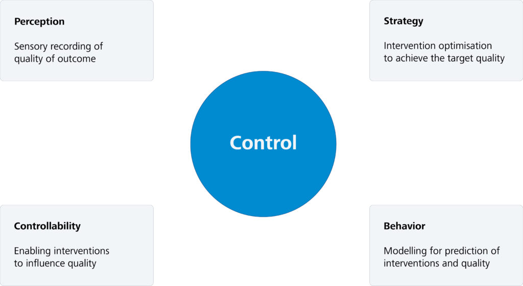
Automatic control of a system requires four central components to be available to solve this task. The first requirement is to define and automatically record target variables that are to be subjected to control. Secondly, the system must possess intervention variables that allow these target variables to be manipulated. Thirdly, it is necessary to understand the quantitative relationship between the target variables and the intervention variables of the system. The fourth requirement is a strategy for adjusting the intervention variables that is capable of steering the target variables into a range determined a priori and keeping them there.

Figure 2 gives an overview of the basic components required for automatic control, which we will look at in more detail below.
- Perception
For some time now, an increasing number of measurement systems have been integrated directly into production lines and manufacturing machines. This makes it possible to capture the quality and process data generated in the manufacturing process at the frequency and density required for effective control. Moreover, the latest research projects are attempting to supplement or replace these measurement systems with so-called virtual measurement technology. These techniques rely on the extraction of quality data from process data using a digital twin of the manufacturing process.
In our example system, the objective is to automatically measure the diameter of the workpiece after production, for example using a laser scanner. In a more complex stage of expansion, the workpiece surface can be digitised in 3D.
- Controllability
In most cases, it is possible to control manufacturing systems at a fundamental level for reasons of practicality. This means that the operator is able to intervene in manufacturing systems and machines in order to control quality-relevant target variables. That said, the ability to automate these interventions is still lacking in many cases, as they often interfere with safety-critical systems. It could also be the case that this feature was simply not envisaged.
In our example system, the distance C is the necessary intervention variable. By changing C, the feed distance stored in the CNC program can be adapted to the tool wear. As a rule, however, this change still needs to be made manually by the machine operator.
- Behaviour
To control the system, it is essential to know how the system’s target variables change when the system’s intervention variables are manipulated. These relationships are summarised in models of system behaviour and can be extremely complex, which is why this aspect of control is a key challenge.
In our example system, the relationship is between the distance C and the final diameter D. This relationship is clearly a linear one, as the tool is at the same height as the axis of rotation. If this were not the case, it would be a non-linear relationship.
- Strategy
The control strategy is responsible for controlling the target variables by adjusting the intervention variables. The relationship between these variables is established by the model used. Reference values and tolerance ranges are available for the target variables, and these must be adhered to for the purposes of quality assurance.
As the system model is inherently incomplete, it is necessary to adapt and correct it as part of the control strategy by means of feedback from the system. Furthermore, the chosen strategy must be able to withstand system disturbances caused by changes in non-modelled external and internal variables in order to ensure that the control objective is achieved despite these influences.
The control strategy for our example system is obvious. As soon as the automatic measurement of the diameter D reveals a deviation from the desired diameter, the distance C is adjusted by the value of this deviation using the opposite sign. However, this approach neglects aspects such as systematic and random measurement errors, which limits the robustness of the method.
As is evident from the above explanations, the aspects of behaviour and strategy pose a particular challenge, both in practical and theoretical terms. For this reason, we will focus on both of these topics in the following two articles. In the next article we will address, among other things, the possibility of automatic modelling of highly complex technical systems, and in the final article we will deal with the development of corresponding robust control strategies.